Tik-76.115 Projektisuunnitelma
CDR-Maker
http://www.hut.fi/~kkonka/oht/
Viimeksi päivitetty 15.10.1998
|
project plan
MDS/CDR Maker Release 1.1
Version 1.0
|
1. Introduction
*
1.1. Project overview
*
1.2. Objectives of the project
*
1.3. Project group
*
1.4. Copyrights and level of publication
*
2. Project Schedule
*
2.1. Project planning
*
2.2. Functional design
*
2.3. Technical design
*
2.4. Prototype 1
*
2.5. Prototype 2
*
2.6. Delivery
*
2.7. After-sales
*
3. Recourses and Distribution of Responsibilities
*
3.1. The whole project
*
3.2 Project planning
*
3.3. Functional Design
*
3.4. Technical Design
*
3.5. P1
*
3.6. P2
*
3.7. Delivery
*
3.8. Cost Estimation
*
4. Work methods
*
4.1. Tools and hardware
*
4.2. Documenting
*
4.3. Methods of project work
*
4.4. Risk management
*
4.5. Roles and tasks of the group members
*
4.6. Information sources
*
5. Management plan
*
5.1. Project monitoring
*
Document version history
|
V# |
By |
Date |
Changes |
Checked
Approved |
|
0.2 |
AH,MS, JK, SV |
14.10.1998 |
Initial version |
|
|
1.0 |
AH, SV, MS |
14.10.1998 |
First release |
PK |
|
1.1 |
SV |
1.11.1998 |
Updating schedule |
PK |
| |
|
|
|
|
Introduction
- Project overview
Oy Comptel Ab’s MDS/CDR Maker is an application that generates Call Detail Records (CDRs) for testing and product development purposes. The idea is to generate test material for several stages in the MDS/AMD-chain. Input CDRs are produced for MDS/ARM (arm_fr, arm_cv, arm_fw), MDS/ARP (make_price) and MDS/ARS (bcall2). Generation rules specify the CDRs.
The MDS/CDR Maker is a product that is used by Oy Comptel Ab’s developers for test, installation, configuration and development purposes. Optionally this application can be used by Oy Comptel Ab’s customers for their test and verification processes.
The aim of this software project is to implement a powerful tool for the MDS/AMD product family. The MDS/CDR Maker should be able to produce input material according to specific record description and generation rules.
CDR consists of several fields. Field properties are for example type, value, coding, byte order, alignment, filler/padding and length. Position of the field is defined inside the record. The length of a field can be defined by number of bits or bytes or set undefined. i.e. size of the value defines length.
User can set generation rules to each record and/or field. Rule is either choice, amount or step rule. Choice rule specifies a record to each defined value (e.g. AA, BB, CC) Amount rule defines the amount of new records. Step rule gives the start value, end value and interval (e.g. from 1000 to 2000 by interval of 150). Unique identifier with label can be generated automatically to each CDR. Date and time values are stepped correctly. Generated CDRs are complement of rules.
Record descriptions and generation rules can be saved, edited and reused.
MDS/CDR Maker is a product that is able to generate CDRs according to specification of a variety of switches in the market. This is possible because of the high level of4 configuration possibilities. MDS/CDR Maker supports ascii-, bin-, ostr-, nstr-, bcd-, bcds-, bcdr-, nstr-, ebcdic-, and ber-encoding. Also MDS/AMDs internal armMsgApi is supported.
The usability of the MDS/CDR Maker is engineer oriented. Since it’s objective is high compatibility with the MDS/AMD environment, it uses command line prompt and emacs-based user interface for configuration.
The name of our project group is Compojat. The name reflects our high spirits and dedication to our company. We understand the need for this tool and therefor are willing to offer our best effort.
Projects home page is on the server of Helsinki University of Technology.
http://www.hut.fi/~kkonka/oht
email:
compojat@
comptel.com
Group Compojat consists of six students that all work for Oy Comptel Ab. The members are as follows:
Role: Project Manager
Name: Santtu Vuori
Phone: 050 353 1121
Email: Santtu.Vuori@comptel.com
Role: Quality Manager
Name: Jukka Koljonen
Phone: 050 592 9530
Email: Jukka.Koljonen@comptel.com
Role: tester, architectural designer
Name: Jaakko Erjanti
Phone: 700 11 502, 050 529 0805
Email: Jaakko.Erjanti@comptel.com
Role: www-administrator, architectural designer
Name: Kai Konka
Phone: 040 526 5631
Email: Kai.Konka@comptel.com
WWW-homepage: http://www.hut.fi/~kkonka
Role: designer, customer contact person
Name: Antti Hänninen
Phone: 050 5 639 639
Email: Antti.Hanninen@comptel.com
Role: head designer
Name: Matti Salonen
Phone: 050 555 6110
Email: Matti.Salonen@comptel.com
People mentioned below are not actual part of the group. Our instructor Kari Sutela is the Section manager of the MDS Research and Development section at Oy Comptel Ab. Our customer contact Pekka Koponen is a software designer in the same section. Also the group will receive some consulting from other Oy Comptel Ab employees.
Role Instructor
Name: Kari Sutela
Phone: 700 11 684
Email: Kari.Sutela@comptel.com
Role: Customer contact
Name: Pekka Koponen
Phone: 700 11 234
Email: Pekka.Koponen@comptel.com
All rights of the MDS/CDR Maker are property of the Oy Comptel Ab. No separate contract is made for the copyrights of this project since all the members have a work contract with Oy Comptel Ab. These contracts clearly define the rights of inventions and projects.
In this stage all documentation is to be published. Oy Comptel Ab Oy reserves all rights for the source code and binaries.
Project Schedule
- Project planning
The aim of planning at this point, is to give all the team members and customer a realistic idea what project is all about and how much effort it’ll take. Project planning is an ongoing process that will end when project is over.
At this stage all functionalities are defined as accurately as possible.
The system architecture is presented and all the relations to other systems are well defined. Before writing the functional description the group must study the customers’ environment to make sure that all necessary interfaces are included in planning. Requirement specification is the basis of functional description. The deadline of this stage is 5.11.1998.
System planning describes the application on a level, which can be considered as an instruction for implementation. In this stage main algorithms are planned and presented, all interfaces described as accurately as possible and the need for test cases is surveyed. During this phase research of required fields (such as BER) must be finished. Architectural design, functional description and test plan must also be finished. Also this is the time to get implementation started. The deadline of this stage is 10.12.1998. In this project planning is done with the help of prototypes. They constitute some stages on the way to the final application. This helps planning and gives an insight into the status of the project.
The purpose of the prototypes is to help planning and minimizing some risks in the project. The customer needs to have an idea of the final application: How it looks and feels. The group can use prototypes to test if some algorithms or architectural ideas work for project. MDS/CDR Maker does not have GUI so main emphasis on the first prototype is to have system architecture ready. During this phase the integration testing should be started, which requires that all the modules have their basic functionality implemented. The deadline of this stage is 22.-23.2.1999.
This prototype is very close to the final application. At the start of this stage we should already have a working program. Now is the time to start testing and repairing and polishing modules towards a wonderful and beautiful program. The deadline of this stage is 19.-21.3.1999.
Finishing the project involves a number of tasks: the documentation needs to be checked, the last demonstration needs to be scheduled and planned, www-pages need to updated and finished. The deadline of this stage is 2 and 5.-6.5.1999. Also all the documents must be finished. In addition a Factory Acceptance Test Plan must be written. This plan is for a customer to test the program’s functionality in the new environment.
Many of the group members will continue working with Oy Comptel Ab and develop this product. Anyway, the program must be easily maintained for other people also. Documents must be so well done that it’ll be easy to support this program.
The people maintaining this program must collect information from bug reports and change requests and take whatever actions needed.
Future development plan includes a graphical user interface.
This release is supposed to be for gathering experiences of usability and program is later to be integrated into the MDS/AMD-product family. For example a graphical user interface will be required later as well user acces controlling.
Recourses and Distribution of Responsibilities
- The whole project
Resources for this project should be calculated with a formula: group size * 200 hours (6 * 200h = 1200 h). Compojat has agreed to work one day each week. This gives us a total of 1260 hours (28 weeks * 7.5 hours * 6 persons). For safety we are however counting on 1400 hours.
| |
Santtu |
Jukka |
Kai |
Antti |
Jaakko |
Matti |
Yhteensä |
|
Planning |
33 |
13 |
11 |
28 |
8 |
23 |
116 |
|
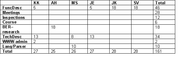
Func.Des |
28 |
28 |
27 |
25 |
27 |
26 |
161 |
|
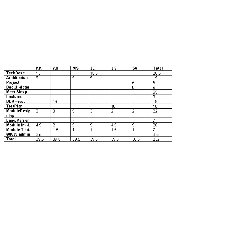
Tech.Des |
39,5 |
39,5 |
39,5 |
39,5 |
39,5 |
38,5 |
234 |
|
P1 |
75 |
75 |
75 |
75 |
75 |
75 |
450 |
|
P2 |
|
|
|
|
|
|
|
|
Testing |
37,5 |
37,5 |
37,5 |
37,5 |
37,5 |
37,5 |
225 |
|
Delivery |
30 |
30 |
30 |
30 |
30 |
30 |
180 |
|
Total |
241 |
221 |
218 |
233 |
215 |
229 |
1366 |
- Project planning
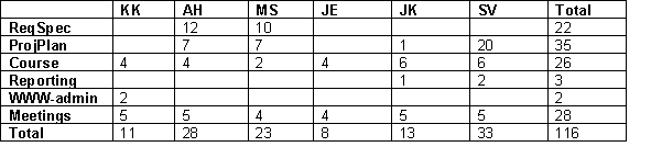
- Functional Design
The project planning phase needs to be complete; both Requirements Specification and Project Plan has to be ready. This phase is used to study the requirements more carefully and making some adjustments to Requirements Specification. All tasks in this phase are divided into clear entities and therefore every person has a good subject to focus in. After this phase we will be able to determine more accurately our schedules.
- Technical Design
At this point it is impossible to estimate work amount required for following steps. So far instead of hours we are using X’s to specify allocation of tasks.
- P1
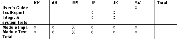
- P2
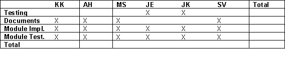
- Delivery
- Cost Estimation
The estimated costs only include the amount of working hours and general costs of company. Licenses and hardware do already exist so they need not be purchased separately for this project. The value of the project is about 175’000 FIM, which consists of six employee’s salary who are working part time for eight months.
Work methods
- Tools and hardware
All the tools and hardware are provided by Oy Comptel Ab.
Program will be done for Hewlett-Packard HP-UX 10.20. Program will later be ported to Digital Unix 4.0D and IBM AIX 4.2.
Tools:
Documenting: Microsoft Word 97
Version control: ClearCase 3.0.2
Compilers: aCC for C++ and gcc for C
CASE-tools: Rational Rose 98, Purify, Pure Coverage, Sniff++
Other: lex, yacc++
Additional Libraries: Roquewave STL-libraries
We use Word 97. The structure of documents is done by instructions received from the course. We will also use some methods of Oy Comptel Ab in addition. Document templates are provided by Oy Comptel Ab.
All documents are reviewed by both the instructor and all the members of the team.
All the documents are shown on our group’s www-page
http://www.hut.fi/~kkonka/oht. Also all the documents have a specific place on a network disc in Oy Comptel Ab, where they are available to all group members and actually to anyone working at Oy Comptel Ab.
The code will be carefully commented. The main functionalities of modules and important class diagrams, interaction diagrams etc. are documented. So everything that significantly helps to understand the structure of the program (and that way helps the maintenance) is documented.
Compojat will have a scheduled meeting once a week, but because all the team members work close to each other, unofficial meetings will take place more often. Group will also keep contact using email and phone.
Instructor meeting will take place every two weeks if needed. Groups instructor works also at Oy Comptel Ab and meets group members almost daily, so unofficial meetings will take place more often.
Group uses normal Oy Comptel Ab method of hour reporting and hour reporting system provided by course.
For error reporting we use a excel work sheet. This sheet is available for everyone on network disk. Everyone have to remember to check the status of the sheet at least once a week. A model of the sheet is represented below.
|
Error |
reported (date) |
reported by |
DL for fixing |
to be fixed by |
fixed (date) |
fixed by |
Extra info |
| |
|
|
|
|
|
v |
|
| |
|
|
|
|
|
|
|
Risks are describer in the table below. This table is constantly under construction throughout the whole project.
|
Risk |
Methods of handling |
Action |
Probability P (1-5) |
Importance I (1-5) |
Weight (P*I) |
|
Change of requirements during the project |
Prototypes, careful design and specification |
|
5 |
4 |
20 |
|
Unrealistic schedule |
Good project plan, be ready for the worst, considering priorities |
Schedule check. Concentrate on tasks with higher priority, |
4 |
3 |
12 |
|
Bad design causes extra work, because modules are not compatible |
Careful inspection of all documents, especially architectural design. |
|
3 |
3 |
9 |
|
Problems controlling the project |
Clear allocation of tasks, emphasize the importance of personal responsibility. |
New allocation of tasks, conversation |
3 |
3 |
9 |
|
The product doesn’t meet the required criteria |
Careful inspection of code and documents. Carefully planned testing. |
|
3 |
3 |
9 |
|
We can’t use certain tools, and loose time learning them |
Allocate tasks to people who already know those tools |
|
2 |
3 |
6 |
|
A member of a group quits in the middle of the course |
Keeping everybody updated what all the others are doing. |
Reassigning the tasks, concentrating on higher priority tasks. |
1 |
4 |
4 |
See 3.2.
MDS/ARM Release 3.4: Functional Description
This document is the Functional Description of MDS/ARM
MDS/ARM Release 3.4: Configuration and Maintenance Guide
MDS/ARM Release 3.4: FR Input Description Language
This document defines the syntax of the File Reader’s (FR) description language.
MDS/ARM Release 3.4: FW Output Description Language
This document defines the syntax of the File Writer’s (FW) description language.
MDS/ARP Version 2.x, Functional Description
This document describer the functionality of MDS/ARP (Account Record Prerating). ARP pre rates incoming CDRs (Call Detail Records).
Roquewave User’s Guide
This document describes the functionality of Roquewave library functions.
ClearCase User’s Manual (Release 3.0 and later)
This is the guide for our version control tool
Manns, Tom: Software Quality Assurance
Pressman, Roger S.: Software Engineering – A Practitioner’s Approach
Management plan
- Project monitoring
The state of the project and the use of resources are monitored in weekly team meetings in which each team member shortly describes his duties at the time and whether he’s on schedule. If anyone in our team encounters problems that are likely to cause his duty to fall behind schedule, he will as soon as possible inform others and the project manager will reallocate resources if he sees it necessary.
The quality of produced documents is monitored with inspections among the team and reviews with the customer. Produced code will be checked in informal walk-throughs in groups of 2-3 persons. Test case covarage is verifyed by by using Purify and PureCoverage applications.
The team will produce prototypes and give demonstrations of the program as defined in the course schedule.