Hannu Arvelo		         arvelo@vipunen.hut.fi
Ismo Kangas		ismo.kangas@research.nokia.com
Riku Linnanen		          riku.linnanen@hut.fi
Janne Pelkonen		    jpelkone@niksula.cs.hut.fi
Jaakko Tiainen		     jtiaine@niksula.cs.hut.fi
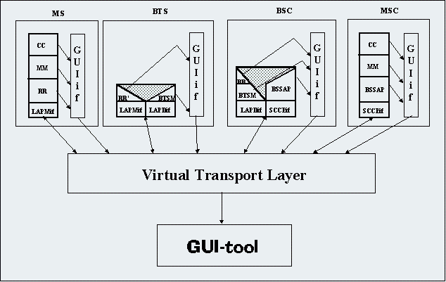
The MobSim project will implement these as protocol stacks, plus a system that demonstrates the signalling traffic going on in the mobile network. The end product will consist of four protocol implementations with a textual user interface and a graphical program to monitor the signalling. Project uses HP-UX with X Windows as developement platform.
MobSim system will be used as a tool to demonstrate selected signalling functionality of a real GSM network. The following functionality will be implemented in the system
The main goal of the project is to provide a means to effectively demonstrate the signalling taking place in a GSM network during these operations. It should be noted, however, that the signaling used is not a complete implementation of the GSM signaling. Signalling is not complete and the signals used are specified using CASN (see below) BER coding, not according to the GSM specifications.
Besides this, the system is intended to serve as an exercise environment for students. The idea is to make additions to the system as an exercise e.g. to add ciphering and authentication signalling to MobSim. It is believed that this kind of environment would be quite realistic - in telecommunications software engineering it is rare to start from scratch. Most often one sets out to enhance and add functionality to an existing system.
The project uses the following main tools:

The main functions of the MobSim components are:
The signalling implemented by the system shows several design choices made during planning of the system:
VTL	3110	lk-hp-16.hut.fi
MSC	1	0	1001
BSC	10	1	2001
BSC	11	1	2002
BTS	100	10	300	20
BTS	110	10	301	30
BTS	120	11	500	60
Environment variable              Meaning
MOBSIM_CONFIG                     Path to MobSim configuration file
MOBSIM_HLR                        Path to MobSim HLR file
MOBSIM_BTS_INDEX                  ID (field 2 in config file) of the BTS
MOBSIM_BSC_INDEX                  ID (field 2 in config file) of the BSC
MOBSIM_MSC_INDEX                  ID (field 2 in config file) of the MSC
MOBSIM_MS_IMSI                    IMSI of the MS to start
MOBSIM_MS_ISDN_NUMBER             Phone number of the MS to start
This example start-up script starts the network elements described in the example configuration file, a single MS with IMSI 000000000000001, phone number 94012345678 and one instantation of the MobSim Monitor program. This example assumes that the various simulator executables can be found in the search path. We have to wait for some time after starting VTL, since we have to ensure that VTL starts listening to its I/O port before we start the various netowork element simulators.
	#!/bin/csh
	setenv MOBSIM_CONFIG mobsim.cnf
	setenv MOBSIM_HLR hlr.dat
	# Virtual Transport Layer
	xterm -e vtl &
        # Wait untill VTL starts listening...
        sleep 5
	# MSC
	setenv MOBSIM_MSC_INDEX 1
	xterm -e mscsim &
        unsetenv MOBSIM_MSC_INDEX
	# BSCs
	setenv MOBSIM_BSC_INDEX 10
	xterm -e bscsim &
        unsetenv MOBSIM_BSC_INDEX
	setenv MOBSIM_BSC_INDEX 11
	xterm -e bscsim &
        unsetenv MOBSIM_BSC_INDEX
        # BTSs
	setenv MOBSIM_BTS_INDEX 100
	xterm -e btssim &
        unsetenv MOBSIM_BTS_INDEX
	setenv MOBSIM_BTS_INDEX 110
	xterm -e btssim &
        unsetenv MOBSIM_BTS_INDEX
	setenv MOBSIM_BTS_INDEX 120
	xterm -e btssim &
        unsetenv MOBSIM_BTS_INDEX
	# MSs
	setenv MOBSIM_MS_IMSI 000000000000001
	setenv MOBSIM_MS_ISDN_NUMBER 94012345678
	xterm -e mssim &
	unsetenv MOBSIM_MS_IMSI
	unsetenv MOBSIM_MS_ISDN_NUMBER
	# Monitor
	gui &
When the various network elements start up, they read the configuration file and HLR file (in MSC) further. For a closer description, see Chapter 4.
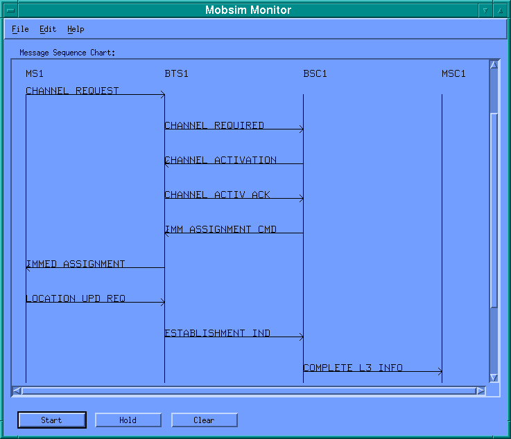
Received message sequence charts can be saved to the disk.
File
Save: Saves the current chart to the disk
Load: Loads a previously saved chart from the disk
Exit: Quits the Mobsim Monitor.
Edit
Clear: Clears the current chart
Filter: Opens the filter dialogue
Help
About: Shows information about the Mobsim Monitor
User can get a detail information of a message by clicking the message arrow. This opens a popup window in which the actual data of that message is displayed.
Beside the drawing area there are scroll bars that can be used to scroll the chart horizontally and vertically if it doesn't fit in the drawing area. Mobsim Monitor provides two scrolling modes: automatic and manual. When the automatic scrolling is on, the drawing area scrolls automatically when a new message is received. The last received message is always displayed on the bottom of the drawing area in that case. In manual mode the drawing area remains static even if new messages are received. User must use the scroll bars to move within the chart.
Start/Stop      Start button turns the monitoring on and Stop button turns it off. When
                the monitoring is on, the Mobsim Monitor records the received messages
                into its data structures and updates the message sequence chart in the
                drawing area.
Scroll/Hold     Scroll button turns the automatic scrolling on and Hold button turns it
                off. In the automatic scrolling mode the drawing area scrolls
                automatically when a new message is received.
Clear           Clear button clears the current chart.

Figure 3. Filter Dialog Box
In the Filter dialog there are there different group boxes, one for each filter type:
Network element -filter  User can select which network elements are visible in
                         the chart.  By default all the elements are visible
Protocol -filter         By protocol filter user can select which protocols are
                         visible in the chart. Each message belongs to one of
                         the five protocols: CC, RR, MM, BTSM, BSSAP.
Mobile station -filter   Each message relates to one mobile station. When there
                         are more than one mobile station in the network, the
                         message sequence chart becomes quite complex. By using
                         the mobile station -filter user can select the mobile
                         stations whose messages he or she wants to be
                         displayed in the drawing area.
In
the filter dialog box there are one toggle button group for each filter type.
If a toggle button is up the respective messages are filtered and they are not
shown in the chart. Mobsim Monitor records every message it receives even if a filter is applied. Applying a filter means only that filtered messages are not shown in the chart.
On the bottom of the filter dialog there is a button panel with three buttons:
Apply                                    Applies the selected filter to the
                                         chart.
Cancel                                   Cancels the changes made in the filter
                                         dialog.
Close                                    Closes the filter dialog.
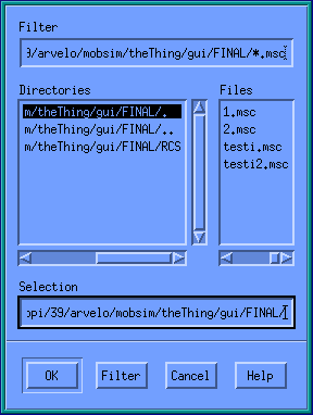
Figure 4. File Selection Dialog Box
These commands are available in MobSim-MS:
call
Give number to call: number
Starts a Mobile Originating Call (MOC) in the mobile station. It sends
CCs_Setup_Req primitive to the CC.
answer
Answers to the Mobile Terminating Call (MOT). It sends CCs_Call_Conf_Req
primitive to the CC.
disconnect
Disconnect call that is already connected or terminates call
establishment phase. It sends CCs_Disconn_Req primitive to the CC.
call
Starts a Mobile Terminated Call in MSC. The user is asked both calling
and called number:
Give calling number: number
Give called number: number
The accepted input is 0-15 numerical characters. This action simulates a
normal telephone user calling a GSM phone under MSC's control. Actions taken in
a successful case (see MSC description for a complete description) are as
follows:
1. Called number analysis
2. Mapping called number onto IMSI
3. Sending CC CCs_Paging message containing IMSI to be found (no connection is
made)
4. CC sends MMs_Paging message to MM (no connection is made)
5. MM sends BSSAP_Paging to BSSAP (no connection is made)
6. BSSAP Fills in needed SCCPS data
7. BSSAP send SCCPS_UnitDataReq message to SCCPS
8. SCCPS part of VTL routes this message to all BSCs
This will start the signalling needed in MTC. In erroneous cases an error
message indicating the cause of the error is given - see Troubleshooting in
description of MSC.
show
Shows a list of all calls currently in progress. This action is mainly
needed for checking the ID number of calls. Useful information of the calls in
progress is also presented with this call.
ID	SOURCE	        DESTINATION
1	950-1234567	90-4775876
2	922-22921	950-1234567
connect
<CVOPS shows a list of active calls, including their ID>
cepID: ID
Simulates network outside of MSC: the call ID has been successfully
connected with the receiving party. Used in conjunction with MOC. In practise
this command sends CCs-CALL-DELIVERED-IND to the CC related with this MOC.
answer
<CVOPS shows a list of active calls, including their ID>
cepID: ID
Also simulates network outside of MSC: the receiving party of MOC
answers the phone. Sends CCs-CALL-CONNECTED-IND to CC.
disconnect
<CVOPS shows a list of active calls, including their ID>
cepID: ID
Closes the connection in question (Disconnect by Network). Sends
CCs-DISC-IND to CC.
AN = alphanumeric field
N = numeric field
Field               Type                Length              Contents
Tag                 AN                  3 + 1 delimiter     `VTL' or `MSC' or
                                                            `BSC' or `BTS'
Id                  N                   6 + 1               VTL: I/O port
                                                            used for sockets
                                                            MSC, BSC, BTS:
                                                            Unique network
                                                            component ID
                                                            number
Info1               AN                  VTL: until EOL      VTL: host name
                                        MSC, BSC, BTS: 6    BSC, BTS:
                                        + 1                 parent's ID
Info2               AN                  10 + 1              MSC, BSC: SCCPS
                                                            point code BTS:
                                                            Location area code
Info3               AN                  10 + 1              BTS: Carrier
                                                            number used
An example of a legal configuration file looks like this:
VTL 3110  lk-hp-16.hut.fi
MSC 1     0      1001
BSC 10    1      2001
BSC 11    1      2002
BTS 100   10     300       20
BTS 110   10     301       30
BTS 120   11     500       60
This would create a GSM network that shown in figure 5.

Figure 5: An example of a MobSim GSM network
Field               Type                Length              Contents
IMSI                N                   15 + 1
CurrCountry         N                   3 + 1               Country code
CurrMSC             N                   6 + 1               MSC Id
CurrLAC             N                   10 + 1              LAC within the
                                                            above-mentioned
                                                            MSC
Number              N                   15 + 1              Phone number
SubsData            AN                  30 + 1              Arbitrary
                                                            subscriber
                                                            information
nCalls              N                   6 + 1               Calls since last
                                                            billing
tCalls              N                   6 + 1               Duration of calls
                                                            since last
                                                            billing, in
                                                            seconds
SubsData field could contain the supplementary services in use, the level of authentication etc. It has as of yes not been implemented in full detail. An exemplary HLR file looks like this:
000000000000001 358 000001 0000000111 9405559114 xxxxxxxxxxxxxxxxxxx 000000 0000000
000000000000002 358 000001 0000000100 9405006868 xxxxxxxxxxxxxxxxxxx 000000 000000000
000000000000003 358 000002 0000000100 9505503305 xxxxxxxxxxxxxxxxxxx 000000 00000000000

Figure 6. Symbols used in MobSim component description
Widget toplevel   Top level shell.
Widget vsb,hsb    Vertical and horizontal scroll bars for the drawing area.
int index         Index to the message list. Its value tells which is the topmost message on the
                  drawing area.
int hor_pos       Value of the horizontal scroll bar.
Display *display  Display of the drawing area.
Window window     Window of the drawing area.
GC gc             Graphic context
int monitoring    1 if monitoring is on. When monitoring is on, received messages are saved in the
                  allMessages-strucuture of the Network class. Monitoring is toggled using the
                  Start/Stop button. Default 0.
int scrolling     1 if autoscroll mode is on. When autoscroll is on, the drawing area scrolls
                  automatically when a new message is received from the socket. Autoscrolling is
                  toggled using Scroll/Hold button. Default 1.
Function             Caller           Action
start_cb()           Start/Stop       Toggles the monitoring variable.
                     button
hold_cb()            Scroll/Hold      Toggles the scrolling variable.
                     button
clear_cb()           Clear button     Frees the memory reserved by the received message sequence.
                                      Calls network.clear() -function and initializes index to 0.
file_cb()            File menu        Load, Save: Opens a File selection dialog box Exit: Exits the
                                      Mobsim Monitor
edit_cb()            Edit menu        Filter: Shows the filter dialog. Calls ShowFilterDlg()-function
                                      from the gui_filter-module. Clear: Calls the
                                      clear_cb()-callback function.
help_cb()            Help menu        About: Shows the information dialog about the Mobsim Monitor.
scroll_action_cb     Scrollbars       Sets index to the value of the vertical scrollbar and hor_pos
                                      to the value of the horizontal scrollbar.
draw_area_cb()       Drawing area     When user clicks the drawing area, rightClick()-function in the
                                      draw-module is called.  Calls the redraw()-function in the
                                      draw-module whenever the window needs to be repainted.
fileopen_cb()        FileOpen         If Ok is choosed in the FileOpen dialog box, calls
                     dialog box       network.load()-function.
filesave_cb()        FileSave         If Ok is choosed in the FileOpen dialog box, calls
                     dialog box       network.save()-function.
SocketHandler_cb()   Socket           Whenever a new message is received from the socket this
                                      callback function is called automatically. It calls
                                      GetNextMessage()-function in the gui_network-module to read
                                      that message from the socket.
MESSAGE_STRUCTURE_SIZE                        Maximum size of the messageList in Network-class.
MAX_NUM_ELEMENTS                              Maximum number of network elements in system.
MAX_NUM_PROTOCOLS                             Maximum number of different protocols in system.
MAX_NUM_MOBILES                               Maximum number of mobile stations in system.
MAX_DATA_SIZE                                 Maximum size of the message data in system.
Networkelement_type                           Type of the network element: MS, BTS, BSC or MSC
ProtocolType                                  Type of the protocol: CC, MM , RR, BSSAP, BTSM
MonitorMessage                                Structure of one message. Includes the source, source
                                              index, target, target index, name, mobile index,
                                              protocol and data of the message.
NetworkElement                                Structure of one network element. Includes type,
                                              index, name and visibility of the element.
Protocol                                      Structure of one protocol. Includes the type, name
                                              and visibility of the protocol.
Network is class that provides all necessary functionality to handle the messages that are received from the socket or loaded from the disk.
MonitorMessage *allMessages                   All the received messages are stored in this data
                                              structure using addLast-member function.
int allIndex                                  Index to the allMessages array. It points to the next
                                              free location in that structure.
MonitorMessage *messages                      All the messages that are not filtered are stored in
                                              this data structure. Member function filter updates
                                              this array.
int index                                     Index to the messages array. It points to the next
                                              free location in that structure.
int ms, bts, bsc, msc                         Number of each network elements that are source or
                                              target of the received messages that are not filtered
                                              out.
all_ms                                        Number of all Mobile stations that are source or
                                              target of the all of the received messages.
NetworkElement *allElements                   All the used network elements are stored in this
                                              array.
int numAllElements                            Number of used network elements
NetworkElement *elements                      All the used network elements, that are not filtered
                                              out, are stored in this array.
int numElements                               Number of used network elements that are not filtered
                                              out.
int getNMessages()                            Returns the number of the message that are not
                                              filtered out.
int getNAllElements()                         Returns the number of the network elements.
int getNElements()                            Returns the number of the network elements that are
                                              not filtered out.
int getNAllMS()                               Returns the nuber of the mobile stations.
int getAllElementNum(int element, int index)  Returns the order number of the element.
int getElementNum(int element, int index)     Returns the order number of the element that are not
                                              filtered out.
char *getAllElementName(int I)                Returns the name of the element i.
char *getElementName(int i)                   Returns the name of the element I that isn't filtered
                                              out.
MonitorMessage *getMessage(int I)             Returns the ith message.
int addLast(MonitorMessage *)                 Appends the received message to the
                                              allMessages-array. If the message passes the filter
                                              then it is appended to the messages-array too.
void addNewElement(Networkelement_type, int   Appends a new network element to the
index)                                        allElements-array. If the elements passes the filter
                                              it is appended to the elements-array too.
void setVisible(int I, Boolean b)             Sets the visibility of the ith network element.
Boolean isVisible(int i)                      Returns the visiblity of the ith network element.
void clear()                                  Clear the Network-class. Empties all the data
                                              sturctures and initializes all the variables.
void filter()                                 Applies the filter to messages. The messages from the
                                              allMessages-list that passes the filter criteria are
                                              copied to the messages-list..
void load(char *filename)                     Loads a saved message sequece chart from the disk.
void save(char *filename)                     Saves the current message sequence chart to the disk.
ProtocolList
int NProtocols                                Number of different protocols.
Protocol *Protocols                           Data structure that stores all the different
                                              protocols.
void SetVisible(int i, Boolean b)             Sets the visibility of the ith protocol.
Boolean isVisible(int i)                      Returns visibility of the ith  protocol.
int getNProtocols()                           Returns the Number of different protocols.
char *getProtocolName(int i)                  Returns the name of the ith protocol.
Network network                               Network variable contains all information about the
                                              gsm-network and the received messages.
ProtocolList protocolList                     Handles the protocols.
int sock                                      Socket to the virtual transport layer.
int CreateSocketConnection(char *host, long   Creates a socket connection to the virtual transport
port)                                         layer. Assigns the sock-variable.
int GetNextMessage()                          Reads the next message from the socket. If the
                                              monitoring is on, parses the received character
                                              string and calls the network.addLast()-member
                                              function to store the message to the
                                              network-structure. Returns 1 if message of a corrcet
                                              type was received succesfully.
Widget filterDialog                           Filter dialog widget.
Static Widget element_buttons[]               Toggle buttons for the element-filter.
Static Widget protocol_buttons[]              Toggle buttons for the protocol-filter.
Static Widget mobile_buttons[]                Toggle buttons for the mobile-filter.
int Position x, y                             Position of the Filter dialog. When the filter dialog
                                              is recreated it can restore the previous position on
                                              screen.
void ShowFilterDlg()                     Shows the filter dialog. If filter
                                         dialog isn't created, creates it.
void UpdateFilter()                      Updates the filter dialog if new
                                         network elements have been added to
                                         the system.
apply_cb()        Apply Button           Apply the filter to the network
                                         elements, protocols and mobile
                                         stations by setting their visibility
                                         property. Then it calls the
                                         network.filter()-member function in
                                         the gui_network-module to filter the
                                         messages.
cancel_cb()       Cancel Button          Cancels the changes user has done in
                                         the filter dialog.
close_cb()        Close button           Closes the filter dialog.
HSPACING                                 Horizontal spacing of the network
                                         elements in the drawing area.
VSPACING                                 Vertical spacing of the network
                                         elements in the drawing area.
LEFTOFFSET                               Left offset of the drawing area.
TOPOFFSET                                Top offset of the drawing area.
void drawArrow(int x1, int y1, int x2,   Draws an arrow from (x1,y1) to (x2,y2)
int y2, char *text)                      and draws the name of the message over
                                         the arrow.
void updateScrollbars(int width,         Updates the the scrollbars of the
height)                                  drawing area.
void redraw(int clear)                   Redraws the drawing area. Calls the
                                         updateScrollbars-function to update
                                         the scroll bars. Draws a selected
                                         protion of the message sequce chart to
                                         the drawing area.  If Clear = 1 then
                                         clears the drawing area first.
void rightClick(int x, int y)            This function is called from the
                                         gui-module when user has clicked in
                                         the drawing area at (x,y). Checks if
                                         user has clicked an arrow, if so,
                                         calls the ShowPopupWindow()-function
                                         in the gui_popup-module to show a
                                         popup window.
DEFAULT_HEIGHT                           Default height of the popup window
DEFAULT_WIDTH                            Default width of the popup window
void ShowPopupWindow(int x, int y,       Creates and shows a popup window at
char *message)                           (x,y).
"new <interface type> connection, fd = ..."to the file associated with the stderr descriptor. The message contains information of the type of the connection, the newly created file descriptor and some type-specific information. If the connecting or initialisation phase fails for some reason, MobSim-VTL tries to recover by closing the newly opened file descriptor. In such case it also sends an error message to stderr. The message contains the information of the failed file descriptor and the type of the interface involved.
4.2.3 Troubleshooting MobSim-VTL
When MobSim-VTL is started, it usually does not need any attention. It just
operates as a switch creating new connections and passing messages between the
existing one. In order to get it started correctly, it is required that the
environment and the configuration file is set up. If there is not enough
information, or the information is inconsistent, MobSim-VTL gives an error
message and exits. When receiving incoming connections and when passing
messages there might happen some kind of error. In such cases MobSim-VTL prints
an error message and closes the file descriptor involved. Here is a
list of the
error messages, and for each an explanation.
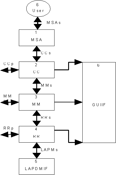
Figure 6. The structure of MobSim-MS
When MobSim-MS process is started ("power on"), it tries to establish connection to the virtual layer. When connection exists between MS and virtual layer, virtual layer sends system information to the MobSim-MS. System information tells cell, location area and channel configuration. If connection establishment is failed, an error message is given and MobSim-MS exists.
4.3.2 The structure of MobSim-MS
MobSim-MS consists of six CVOPS vtasks. Three of them (RR, MM and CC)
represent GSM protocols, two represent interfaces to MobSim-VTL (LAPMIF and
GUIIF) and one acts as the user interface of MS (MSA).
The CVOPS implementation of RR-protocol consists of:
The CVOPS implementation of MM-protocol consists of
The CVOPS implementation of CC-protocol consists of
The CVOPS implementation of LAPMIF-protocol consists of:
The CVOPS implementation of GUIIF consists of:
See Chapter 3.2.2 for a closer look on these commands.
The CVOPS implementation of MSA consists of:
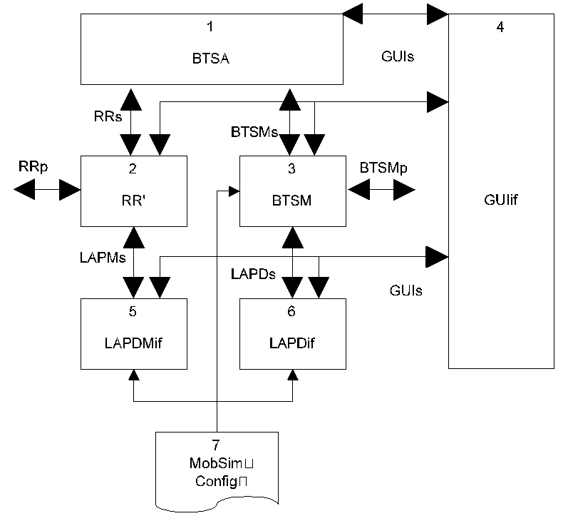
Figure 7: Structure of MobSim-BTS
4.4.1 Invoking MobSim-BTS
When MobSim-BTS is started, it behaves like a normal CVOPS system. The system
can be operated by using the CVOPS command interpreter. Initially, the system
is set up by giving it the CVOPS run-command, which asks user the protocol
structure file. This initialisation step is automated by defining a specific
macro called CVOPS_init in the CVOPS default macro file macro.mac. A
sample macro file containing this initialisation macro looks like:
	$CVOPS_init$
	run
	bts.str
	macro end
When the vtasks of MobSim-BTS are initialised, they read the general Mobsim configuration file. MobSim-BTS needs information of the network addresses of itself and the BSC it is connected to. It also needs to know the indices of the BTSs, which it controls. In order to find out the name of the configuration file, it checks the environment variable named MOBSIM_CONFIG, which should contain it. MobSim-BTS needs also knowledge of its own index in the file. The index must be given in the environment variable named MOBSIM_BTS_INDEX. See chapter 3.1 for more information and an example configuration file. For example, the MobSim-BTS with index 110 can be found in the file, and there exists a BSC for it also. If either of the environment variables is absent, or if MobSim-BTS cannot find the information it needs from the configuration file, a short error message is given and MobSim-BTS then exits.
After MobSim-BTS has successfully read the needed information from the configuration file, both of its interface vtasks try to connect to the virtual transport layer. Again, if there happens some error during making the connections, a short error message is given and MobSim-BTS exits.
4.4.2 The structure of MobSim-BTS
The structure of MobSim-BTS has its roots in the role of BTS as a bridge
connecting
mobile stations and the network. BTS relays messages between two quite
different interfaces, namely the Air interface and the A-bis interface. The
MobSim-BTS, however, simplifies this situation by defining the protocol stack
only down to LAPM and LAPD interfaces, where the physical differences are well
hidden.
MobSim-BTS consists of six CVOPS vtasks. Two of them (BTSM, RR') represent GSM protocols, one is has the conversion logic between the Air and A-bis interfaces (BTSA), and three are interfaces to MobSim-VTL (LAPDIF, LAPMIF and GUIIF).
The function of BTSM vtask is to receive controlling messages from the BSC counterpart. These controlling messages drive the whole element. BTSM uses LAPD services and provides its own services for BTSA. Since LAPD only provides a two-way data communication service, BTSM operations are mainly controlled by BSC BTSM PDU's and BTSM primitives triggered by BTSA.
The function of BTSA vtask is to provide a link between RR' and BTSM. Since not all related BTSM and RR data types are matching, some data manipulation is necessary. Since BTSA is connection-oriented, and RR' is not, some special attention needs to paid. In this case, the sole responsibility for correct CEP_id matching is left to RR'.
The function of RR' is to relay messages from and to the mobile station using the correct channel. While most of the messages received are passed on intact, some pdus have to be changed. The pdus listed below are transformed:
Direction                  Received PDU               Transmitted PDU
Uplink                     CHANNEL_REQUEST            CHANNEL_REQUIRED
Downlink                   IMM_ASSIGNMENT_CMD         IMMED_ASSIGNMENT
Downlink                   PAGING_COMMAND             PAGING_REQUEST
Downlink                   BCCH_INFORMATION           SYSTEM_INFORMATION 1-4
Downlink                   SACCH_FILLING              SYSTEM_INFORMATION 5-6
To cope with the connection-oriented BTSA, RR' must do some bookkeeping. It has to preserve the CEP_id and the related channel information every time BTSA sends information, so the correct CEP_id can be found via matching channels.
During channel assignment, MS sends a layer 2 pdu to the BTS, which RR' sees as a primitive from LAPM. RR' generates ESTABLISHMENT_INDICATION pdu, which is then transferred to BSC.
LAPD-interface virtual vtask provides the data transfer service for MobSim-BTS's BTSM. When LAPDIF hooks itself to the VTL, it tells its index and the corresponding BSC index for addressing.
LAPDIF does not provide other services than data request and data indication.
LAPM-interface virtual vtask provides the data transfer service between MobSim-BTS's RR' and MSs. When LAPMIF fires up, it reads the carrier number from the config file. LAPMIF provides data transfer and link establishment services.
The CVOPS implementation of GUIIF consists of:
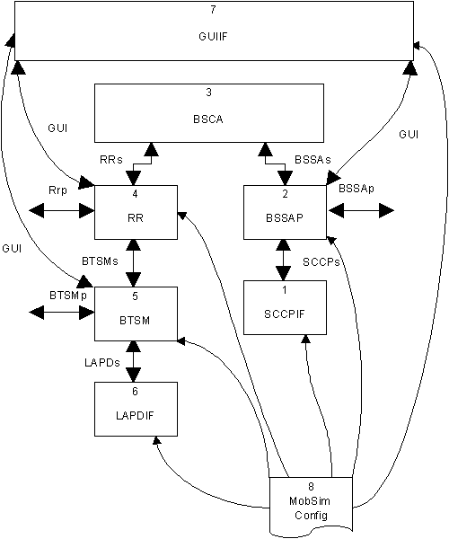
Figure 8: Structure of MobSim-BSC
4.5.1 Invoking MobSim-BSC
When MobSim-BSC is started, it behaves like a normal CVOPS system similar to
that described in chapter 4.4.1. When the vtasks of MobSim-BSC are initialised, they read the general Mobsim
configuration file. MobSim-BSC needs to know the host name and the IP port
number of the Virtual Transport Layer . It also needs information of the
network addresses of itself and the MSC it is connected to. Further, it needs
to know the indices of the BTSs , which it controls. In order to find out the
name of the configuration file, it checks the environment variable named
MOBSIM_CONFIG, which should contain it. MobSim-BSC needs also knowledge of its
own index in the file. The index must be given in the environment variable
named MOBSIM_BSC_INDEX. See chapter 3.1 for more
information and an example configuration file. For example, the MobSim-BSC with
index 10 can be found in the file, and there exists an MSC for it also. If
either of the environment variables is absent, or if MobSim-BSC cannot find the
information it needs from the configuration file, a short error message is
given and MobSim-BSC then exits (see Troubleshooting MobSim-BSC).
After MobSim-BSC has successfully read the needed information from the configuration file, all of its interface vtasks try to connect to the Virtual Transport Layer. Again, if there happens some error during making the connections, a short error message is given and MobSim-BSC exits (see Troubleshooting MobSim-BSC).
4.5.2 The structure of MobSim-BSC
MobSim-BSC is a relay element,
with two different kinds of external interfaces defined in GSM specifications.
This comes from the fact that a GSM BSC relays messages from MSC to MS via BTS.
BSC also communicates itself with MS and BTS when it comes to the management of
radio resources. The interfaces between the vtasks of MobSim-BSC are defined
using the ASN.1 language. An interface is defined by a set of service
primitives. The protocol data units (pdu) are passed within these service
primitives. The protocol specific pdus are part of the protocol specification
and are defined formally, whereas the service primitives are typically
implementation-specific. The pdus need to be formally defined because they are
eventually passed to the peer entity in the other network element.
All the pdus which are received and decoded are also sent to the GUIIF vtask. GUIIF decodes the pdu it receives, and sends a message to Virtual Transport Layer which routes the messages to the active GUI-tools. The message contains information of the sender and the receiver of the pdu and also an ASCII-form tracing of the contents of it.
CVOPS implementation of MobSim-BSC consists of seven CVOPS vtasks. Three of them are GSM protocol implementations (BTSM, RR and BSSAP), one has the conversion logic between A-bis and A interfaces (BSCA), and three are interface vtasks to MobSim-VTL (LAPDIF, SCCPIF and GUIIF).
The CVOPS implementation of BTSM-protocol consists of:
The CVOPS implementation of BSSAP-protocol consists of:
The CVOPS implementation of RR-protocol consists of:
The CVOPS implementation of SCCPIF consists of:
The CVOPS implementation of LAPDIF consists of:
The CVOPS implementation of GUIIF consists of:
The CVOPS implementation of BSCA consists of:
4.5.3 Procedures in MobSim-BSC
MobSim-BSC operates similarly as a real BSC like a relay element between MSC on
one side and MSs plus BTSs on the other. BSC does not get involved directly in
the procedures between MSC and MS. It merely gets instructions from MSC in
BSSAP protocol, which is interprets, and acts accordingly. It also manages the
radio resources of the BSS. The procedures in MobSim-BSC are:
4.5.4 Troubleshooting MobSim-BSC
BSC provides varius error diagnostics. Each time an error occurs a message
is printed on the screen and BSC exits. The MobSim-
BSC error list contains all error messages of BSC.
A real MSC always has Visitor Location Register (VLR) containing central information needed for operation of MS outside of their own HLR area. There is no VLR as such in MobSim, since it only simulates one MSC.
MobSim's MSC consists of five CVOPS virtual tasks. Three of these represent GSM protocols, one is an interface to the virtual layer (SCCPSIF), and one manages MSC. This management vtask we will call MSC Application (MSCA), or just Application. Application is responsible for bookkeeping, checking that called numbers make sense (number analysis) and simulating networks outside of MSC. Figure 9 presents the structure of MobSim-MSC.
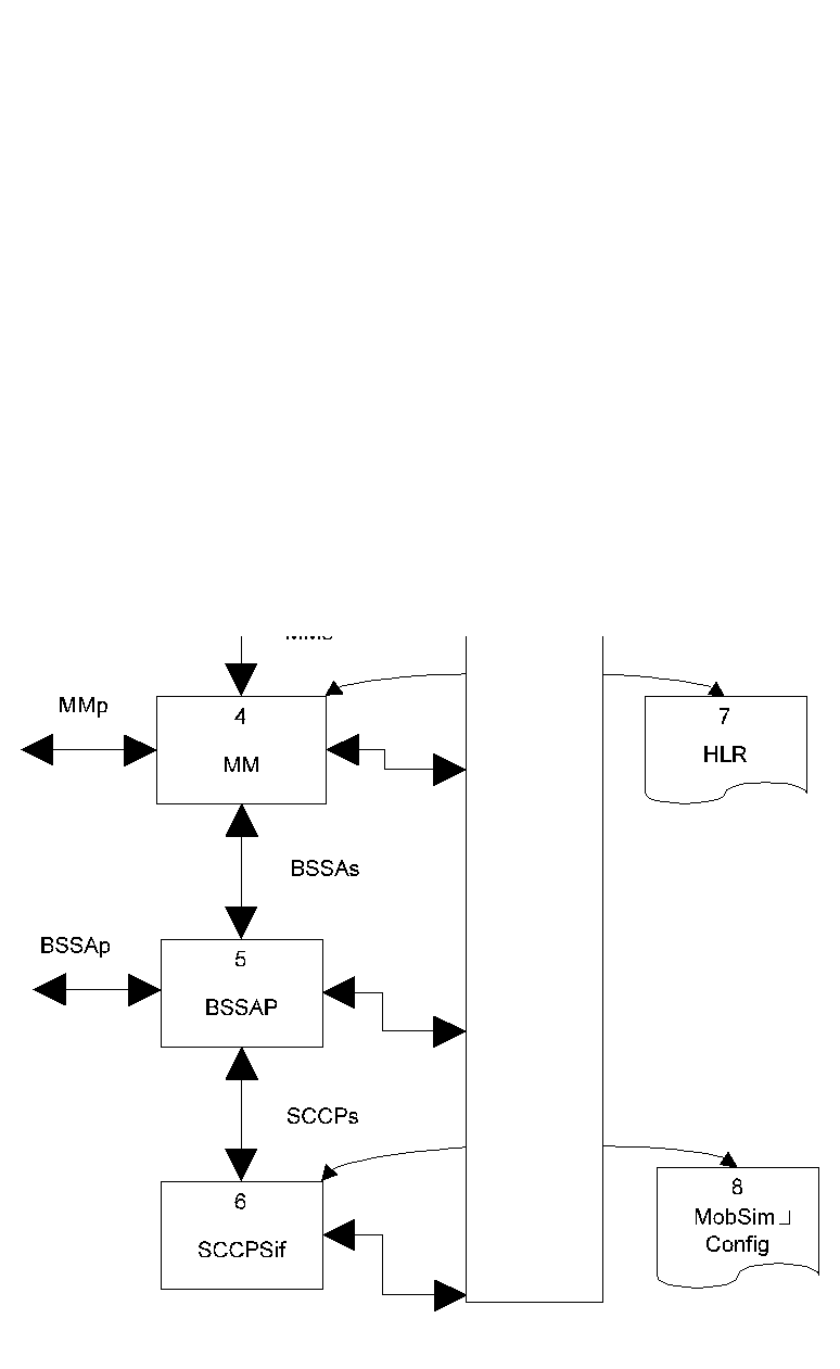
Figure 9: Structure of MobSim-MSC
4.6.1 Invoking MobSim-MSC
When MobSim-MSC is started, it behaves like a normal CVOPS system similar to
that described in chapter 4.4.1.
When the vtasks of MobSim-MSC are initialised, they read the general Mobsim
configuration file. MobSim-MSC needs to know the host name and the IP port
number of the Virtual Transport Layer . It also needs information of the
network addresses of itself. Further, it needs to know the indices of the BSCs
which it controls. In order to find out the name of the configuration file, it
checks the environment variable named MOBSIM_CONFIG, which should contain it.
MobSim-MSC needs also knowledge of its own index in the file. The index must be
given in the environment variable named MOBSIM_MSC_INDEX. See chapter 3.1
for more information and an example configuration
file. For example, the MobSim-MSC with index 1 can be found in the file. If
either of the environment variables is absent, or if MobSim-MSC cannot find the
information it needs from the configuration file, a short error message is
given and MobSim-MSC then exits (see Troubleshooting MobSim-MSC).
After MobSim-MSC has successfully read the needed information from the
configuration file, all of its interface vtasks try to connect to the Virtual
Transport Layer. Again, if there happens some error during making the
connections, a short error message is given and MobSim-MSC exits (see
Troubleshooting MobSim-MSC <href chapter Troubleshooting MobSim-MSC).
4.6.2 The structure of MobSim-MSC
The CVOPS implementation of MobSim-MSC consists of six CVOPS vtasks. Three of
them represent GSM protocols (BSSAP, MM and CC), one is the user interface to
MSC (MSCA) and two are interfaces to MobSim-VTL (SCCPSIF and GUIIF).
The CVOPS implementation of SCCPIF consists of:
The purpose of SCCPS vtask if to connect MSC to BSCs under its control. SCCPS routes messages between MSC and BSC according to SCCPS addresses, which consist of a pair of a point code and a subsystem address. Every MSC and BSC has its own point code, which is defined in the MobSim configuration file.
Upon reception of SCCPS connection-oriented message (location updating, mobile originated call, paging response), SCCPS decodes it long enough to find out the calling and called address and reserves a connection between these. Hereafter all data messages pertaining to this connection will use this connection. SCCPS disconnect message frees the connection.
A Special case in SCCPS is paging, which is handled as connectionless data. Paging requests are sent to all BSCs as unit data. Upon finding the requested MS, the right BSC sends a normal SCCPS connection message - see paging response above.
The CVOPS implementation of GUIIF consists of:
The CVOPS implementation of BSSAP-protocol consists of:
The duties of BSSAP include communication between MSC and BSC plus transmitting data to MM and CC. BSSAP connection is started by BSC closed by the MM protocol. Paging data goes through the BSSAP entity automaton as connectionless data.
BSSAP receives two kinds of messages from the DOWN interface: SCCPS_Conn_Ind
(connection primitive, which also contains the first PDU) and SCCPS_Data_Ind.
They are decoded as follows:
1. Decode as BSSAP_Msg
2. If transparent bit is set to zero, this is a BSSAP message, which is decoded further
3. If transparent bit is non-zero, MM connection is created and
BSSAs_Compl_L3_Info service primitive containing the message is sent to MM
Encoding in BSSAP follows an analogous procedure in reverse direction. Messages to peer interface are marked as transparent=0, whereas Layer 3 data received in BSSAS_Data_Req is marked as transparent=1. Besides this encoding and decoding procedure BSSAP does not do significant processing, it mainly transmits data to Layer 3.
MSC performs paging by first transmitting IMSI to BSSAP protocol, which in turn checks HLR for the LAC of this the MS corresponding to this IMSI. With this LAC, we can find the network config file the BTS to which the MS has recently been connected to. In the network configuration file we can find the BSC and its point code which controls this BTS. After these searches we are ready to send Paging Request to (presumably) right BSC - see Chapter 4.6.3 for a flow chart of this procedure.
The CVOPS implementation of MM-protocol consists of:
The role of MM protocol in different MobSim-MSC procedures is described in chapter 4.6.3.
The CVOPS implementation of CC-protocol consists of:
The CVOPS implementation of MSCA consists of:
4.6.3 Procedures in MobSim-MSC
Here we will present the steps taken by MSC as a whole during MobSim's various
tasks using flow charts.
4.6.4 Troubleshooting MobSim-MSC
MSC provides varius error diagnostics. Each time an error occurs a message
is printed on the screen. Some of the errors are so severe that they
cause MSC to exit. The MobSim-
MSC error list contains all error messages of MSC.