| Dynamics |
| Project Plan |
$Revision: 1.7 $ |
State approved |
| Date 10-Dec-1998 |
Author Tom Weckström |
| Review date 10-Dec-1998 |
Reviewed by Jouni Malinen |
| Approval date 10-Dec-1998 |
Approved by Jouni Malinen |
$Id: proj_plan.html,v 1.7 1998/12/10 09:05:20 jkmaline Exp $
Executive summary
This is a project plan document for the Dynamic IP-tunnel project
carried out at the HUT course Tik-76.115 (Software project) during the
academic year 1998-1999. The project concentrates on mobility
management and IP-protocol tunneling of a mobile computer using
IPv4-protocol in network connections. The goal of the project is to
develop a well working prototype that may easily be further
developed. The software produced in the project shall enhance the
mobility management of mobile computers. The tunnels shall be
hierarchical and dynamically updated.
At the end of the project the software shall also have APIs as well
as management and configurations tools. The project will be carried
out by a group of six students of computer science. This document is a
controlling tool for managing the software project. It specifies the
technical and managerial processes and activities necessary to satisfy
the project requirements.
Index
1. Introduction
1.1 Project
definition
1.2 Project
goals and deliverables
1.3 Project
team
1.4 Rights
to the project deliverables
1.5 Evolution
of the project plan
1.6 Terms,
definitions and acronyms
2. Project phases and scheduling
2.1 Project
planning (PS)
2.1.1 The
PS phase main deliverables, their detail levels and meanings
2.1.2 The
main tasks of the PS phase
2.2 Definition
(MÄ)
2.2.1 The
MÄ phase main deliverables, their detail levels and meanings
2.2.2 The
main tasks of the MÄ phase
2.3 Design
(SU)
2.3.1 The
SU phase main deliverables, their detail levels and meanings
2.3.2 The
main tasks of the SU phase
2.4 Prototype
1 (P1)
2.4.1 The
P1 phase main deliverables, their detail levels and meanings
2.4.2 The
main tasks of the P1 phase
2.5 Prototype
2 (P2)
2.5.1 The
P2 phase main deliverables, their detail levels and meanings
2.5.2 The
main tasks of the P2 phase
2.6 Delivery
(LU)
2.6.1 The
LU phase main deliverables, their detail levels and meanings
2.6.2 The
main tasks of the LU phase
2.7 Product
treatment after the project
3. Resources and work
distribution
3.1 Resources
available for the entire project
3.2 Resources
for the Project planning phase (PS)
3.3 Resources
for the Definition phase (MÄ)
3.4 Resources
for the Design phase (SU)
3.5 Resources
for the Prototype 1 phase (P1)
3.6 Resources
for the Prototype 2 phase (P2)
3.7 Resources
for the Delivery phase (LU)
3.8 Cost
estimation
4. Working methods
4.1 Software
tools and hardware resources
4.2 Documentation
methods
4.3 Project
working methods
4.4 Risk
management
4.5 The
roles and responsibilities of the team members
4.6 References
5. Project steering
and progress management
5.1 Project
measurement
5.2 Project
schedule steering
1. Introduction
This is a project plan document for the Dynamic IP-tunnel project carried
out at the HUT course Tik-76.115,
Software project during the academic year 1998-1999. This document
is a controlling tool for managing the software project.
This chapter introduces the Dynamic IP-tunnel project. In the Introduction
chapter the project is defined, its primary goals are stated, the project
team is introduced and the terms and the evolution of the project plan
are defined.
1.1 Project definition
Wireless LANs, protocol tunneling and mobility management are areas of
growing interest these days. Mobile users roaming in foreign networks with
their laptop computers is a trend of the future. Roaming mobile users are
willing to get the same services as they would get when attached to their
office LAN using Ethernet and IP-protocol.
In dynamic IP-tunnel project (from this on called "project" in this
document) a group of software components (from this on "the software")
is developed to allow transparent routing of IPv4 datagrams to mobile nodes
in the Internet. Each mobile node is always identified by its home address,
regardless of its current point of attachment to the Internet.
The project deliverables may be used in the MART-project
represented by Jari T. Malinen. The deliverables might also be of use in
other projects concentrating on mobile IP, IPv4-tunneling, IP-routing,
etc. Also, results from another ongoing software project, the mobile user DNS project,
might be integrated to the tunneling environment and thus
enhance the services offered for mobile users.
While situated away from its home, a mobile node is also associated
with a care-of address, which provides information about its current point
of attachment to the Internet. The home agent sends datagrams destinated
to the mobile node through a tunnel to the care-of address.
This document is subject to change as the project proceeds. Project
manager Tom Weckström is responsible for the consistency of this document
with the current situation in the project.
1.2 Project goals and
deliverables
The primary goal of the project is to make a working, well documented product
that satisfies the requirements and quality expectations. If the project
succeeds, the prototype produced during the project may be used in the
further development of the dynamic IP-tunneling.
The other goals of the project, when achieved, lead to the primary goal
step by step. The other goals are, in brief:
-
To make it easier to move with a computer attached to IPv4-network
-
To provide a scalable solution for IP-tunneling
-
To reduce the tunneling system administration effort from that of maintaining
the tunnels manually
-
To provide analysis possibilities for administrators and configurability
to both users and administrators.
The main deliverables of the project shall be:
-
Tunneling system architecture elements. The pieces of software needed in
different parts of the tunneling system.
-
API. To ease the development of system support tools.
-
Configuration, maintenance and monitoring software.
-
System and project documentation.
1.3 Project team
The Dynamic IP-tunnel project team Dynamics consists of six students of
computer science from the HUT. The customer and the instructor will give
their assistance in problematic situations. Communication between the project
team, the customer and the instructor shall be active.
The project steering group consists of the customer, the instructor,
the course personnel (Kari Alho, Reijo Sulonen and Jari Vanhanen) and the
project team.
The web pages of the project team Dynamics
are available at http://www.hut.fi/~kmustone/dynamics/
The email address of the project team is dynamics@nukkekoti.cs.hut.fi.
In case you would like to contact the team members, the customer and the
instructor, please send email to all-dynamics@nukkekoti.cs.hut.fi
Below you can find information about people involved in the project.
1.4 Rights to the
project deliverables
A separate contract on rights of using, developing and selling the products
developed during the project will be made after the project team has consulted
Mr. Olli Pitkänen, who will give a lecture on project rights on 15th
October 1998.
The customer has agreed on delaying the final formal agreement until
the project team has sufficient knowledge of writing a clear, unambiguous
contract to be signed.
As default, however, the project team members retain all the rights
for the project deliverables. The customer will get rights to use and develop
the product in non-commercial projects.
1.5 Evolution of the project
plan
This project plan document will be continually updated as the project progresses.
Each change shall have an effect on the version number. At the end of the
project the general evolution overview of the whole project shall be possible
by reading this document. The scheduled update dates for this document
are at the end of each project phase:
-
15th October 1998
-
5th November 1998
-
10th December 1998
-
18th February 1999
-
25th March 1999
-
22th April 1999
There may also be unscheduled updates to this document between the scheduled
updates.
1.6 Terms, definitions
and acronyms
The terminology of this document and the whole project will follow the
terminology used in the Requests For Comments documents of the mobile IP
and IP-tunneling field, especially [RFC2002].
The terminology, definitions and acronyms are defined in a separate
terminology specification to which all the other
documents can refer.
2. Project phases and scheduling
The project phases and scheduling are clarified in this chapter. For each
phase the main tasks are introduced, deliverables are defined, reports
and other documents are declared and their detail levels are defined.
The project starts on 17th September 1998 and ends on 6th May 1999.
The project is divided into six (6) phases:
| Project phase |
Phase code |
Duration |
| Project planning |
(PS) |
3 weeks |
| Definition |
(MÄ) |
3 weeks |
| Design |
(SU) |
5 weeks |
| Prototype 1 |
(P1) |
5 weeks |
| Prototype 2 |
(P2) |
5 weeks |
| Delivery |
(LU) |
4 weeks |
Each phase is further divided into specific task related A.b/c codes.
The A part of the code defines the phase of the project. Each phase is
divided into main operational areas defined with b level codes. Some
of the b level codes are further divided into several c level codes. The
c level codes are very close to the actual Todos of the phase. Todos are
practically same as tasks. Please refer to the project
Work Breakdown Structure (WBS) for a concrete view of the project work
flow. In the project WBS each main activity has it's own primarily responsible
person. This naming convention reduces the risks 4.4.1.1.1
(Responsibilities not clear enough) and 4.4.1.1.2
(Missing responsibility areas).
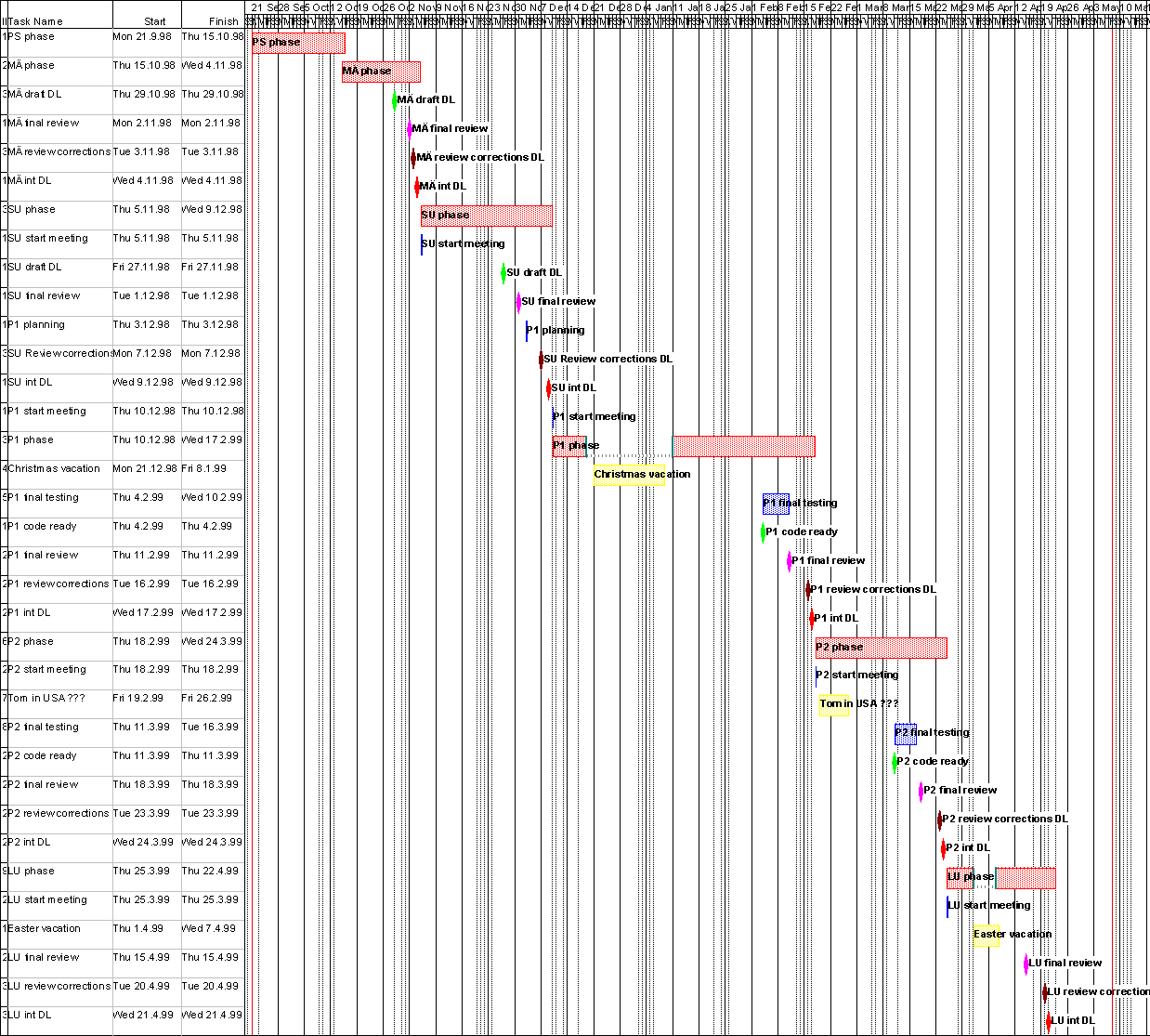
The schedule of the project is easy to realize from the Gantt
chart of the project. The Gantt chart is also available in PostScript
format.
The plans for each phase shall be defined more accurately in the next
versions of this project plan as the project goes on. Project manager Tom
Weckström is responsible for updating the phase and scheduling information
and tasks in this document. Also more detailed scheduling information will
be added to this document.
2.1 Project planning (PS)
The PS phase starts on 17th September 1998 and ends on 15th October 1998.
During this phase:
-
A project is chosen
-
The project is organized
-
The requirements are specified
-
The project is planned
-
The preconditions for a successful project are established
-
The next MÄ phase is planned
At the end of the phase the project goals, scope, environment, organization,
scheduling and all other issues should be clarified and documented. The
team should be ready to work efficiently in the next phase.
2.1.1
The PS phase main deliverables, their detail levels and meanings
Project manager (TWE) is responsible for the completion of the deliverables
of PS phase.
-
Project plan
Project plan should be as detailed as possible. However, since the
project plan will evolve, some optimization should be done to prevent unnecessarily
detailed planning of the distant phases. The project plan concentrates
on the managerial issues of the project. A good project plan should help
the team to achieve the goals at each phase. The project plan is especially
a tool for the project manager.
-
Requirements specification
At the PS phase the requirements should be general enough to prevent
too tight commitment to any detail that is not yet clear. The requirements
of the customer are defined, analyzed, prioritized and documented. The
aim is to figure out what this project really should produce.
-
Progress report
This report helps to plan the following phases, gives feedback about
the previous phase and the efficiency of the team. Progress report is also
a tool for the customer, the inspector and the course personnel to monitor
the state of the project. Progress report shall define the state of the
project and list the completed tasks.
Additional deliverables belonging tightly to one or more of the main deliverables:
-
Terminology specification document
-
Quality policy document
-
Requirements table
-
Meeting minutes
2.1.2 The main tasks
of the PS phase
This section describes the main tasks, their influence on the project
deliverables and the responsible persons for each task.
The entities or deliverables influenced by the tasks are the PS deliverables:
Project plan (pp), Requirements specification (rs) and project organization
(po) and customer relations (cr) and the working environment (we).
The responsibilities are defined according to the name initials and
"all" is marked when everyone is responsible for the task in question.
The main tasks are divided into smaller tasks that are found in the
PS phase progress report document.
The main tasks of the PS phase are:
-
Lectures
-
Responsibility: all
-
Influence: po, pp, rs
-
Organization
-
Responsibility: TWE
-
Influence: po, pp
-
Meetings
-
Responsibility: TWE, all
-
Influence: po, cr, pp, rs, we
-
Studying
-
Responsibility: all
-
Influence: rs, pp, future
-
Project plan
-
Responsibility: TWE, parts for others
-
Influence: pp, po
-
Requirements specification
-
Responsibility: TWE, parts for others
-
Influence: rs, pp, po
-
Equipment analysis
-
Responsibility: JMA
-
Influence: we
-
Other tasks
-
Responsibility: all
-
Influence: all deliverables and entities of the PS-phase.
2.2 Definition (MÄ)
The idea of the MÄ phase is to define the software as well as possible
before the beginning of the system design. The most emphasis is put on
the external interfaces of the software, i.e. the interfaces to other systems,
the functionality of the API, the user interfaces etc.
The MÄ phase starts on 15th October 1998 and ends on 5th November
1998.
At the end of the MÄ phase the system has been defined so that
the more detailed desing phase may begin.
2.2.1
The MÄ phase main deliverables, their detail levels and meanings
The system designer (BAN) and project manager (TWE) are responsible for
the completion of the deliverables of the MÄ phase. The deliverables
and responsibilities are defined below:
-
Functional definition
The functional definition relies strongly on the requirements specification.
The software architecture, functional environment, functionality, system
information and the information flows shall be defined. Functional definition
shall be the core of the design phase.
Responsible: BAN
-
Project plan
The project plan shall be further defined. The project planning shall
be reached further to the future and all changes in the situation shall
be documented.
Responsible: TWE
-
Requirements specification
The requirements specification may be reviewed. The definition of the
system may change the original requirements and thus the priorities, formulation
and definition of the requirements shall be revised.
The aim is to have a requirements specification that would remain unchanged
till the end of the project.
Responsible: TWE
-
Progress report
The progress report shall be revised to define the current state of
the project. A list of the tasks completed in the MÄ phase shall be
added. Progress report shall help to verify that the project is in schedule.
It shall also help in estimating the resource allocation situation and
planning the future actions.
Responsible: TWE
Additional deliverables belonging tightly to one or more of the main deliverables:
-
The terminology specification document shall be revised
-
Requirements table shall be updated from the requirements specification
document
-
Meeting minutes of the MÄ phase
-
Project WBS (project A.b/c codes)
-
Project Gantt chart
-
Quality plan shall be revised
-
Figures, diagrams, flowcharts and other documents explaining the system
architecture
2.2.2 The main tasks
of the MÄ phase
This section describes the main tasks of the MÄ phase. In addition
to the general activities like meetings, course lectures and documentation,
the MÄ phase activities contain lots of definition work. All the components
of the system are defined and protocols and interfaces are described.
The project WBS document gives a good
picture of the MÄ phase activities. The activities of the MÄ
phase start with an A level code 2.
The activities are further split to smaller tasks each having clearly
one responsible person and a well defined task output. The complete task
description with estimated and consumed hours is available at the project's
MÄ phase progress report.
2.3 Design (SU)
The SU phase starts on 5th November 1998 and ends on 10th December 1998.
The SU phase will continue the work started in the MÄ phase. In
the SU phase the definitions shall be further specified to form design
entities.
During the SU phase the software shall be designed so that the implementation
may begin without any obstacles in the Prototype 1 phase. Also, an alpha
1 prototype of the software will be implemented.
The alpha 1 prototype shall concentrate mainly on IP-over-IP tunneling
issues. The basic idea of the prototype is to reduce the risks. The alpha
prototype will be a good probe to find out the correlation between the
customer expectations and the current state of the product. The most difficult
parts of the project should be tackled at the early phase of the project
to reduce risks and expensive corrections in late phases. Some difficult
questions:
How two IP tunnels can
be connected?
How the encapsulation-decapsulation-encapsulation
scheme will work?
2.3.1
The SU phase main deliverables, their detail levels and meanings
The system designer (BAN), Test manager (KMU) and project manager (TWE)
are responsible for the completion of the deliverables of the MÄ phase.
The deliverables and responsibilities are defined below:
-
Functional definition
The functional definition shall be revised.
Responsible: BAN
-
Project plan
The project plan shall be further defined.
Responsible: TWE
-
Technical design definition
A detailed design document describes the architecture, processes, modules
and the detailed module design.
Responsible: BAN
-
Testing plan
Covers the test targets, testing environment, test organization, test
reports, test cases and modules, approval criteria for testing and the
testing of nonfunctional features.
Responsible: KMU
-
Progress report
The Progress report shall be revised to represent the current state
of the project.
Responsible: TWE
-
Alpha prototype
The alpha prototype will describe the IP-tunneling environment in a
simple demonstration of three tunneling elements. Alpha prototype should
prove that the chosen approach is fruitful for the desired product.
Responsible: BAN
Additional deliverables belonging tightly to one or more of the main deliverables:
-
The terminology specification document shall be revised.
-
Meeting minutes of the SU phase
-
The alpha prototype documentation
-
State machines and state machine pictures of the system elements
-
Pseudocode presentations
-
Other related documents like test report templates, error report templates
etc.
2.3.2 The main tasks
of the SU phase
The SU phase activities are defined in the project
WBS document. The SU phase activities has the A level code 3 in their
A.b/c codes.
Aside of the WBS, the following list works as a checklist for the actions
that might be necessary in the SU phase:
-
Defining a general description of the dynamic IP-tunneling field
-
Finding more references to project related standards
-
Designing the interfaces of the system
-
Designing the functions of the system
-
Designing the architecture of the system
-
Database architecture
-
Modules and processes
-
Reusable parts of the system
-
Descriptions of the modules and processes
-
General description
-
Interfaces
-
User interfaces
-
Behavior in error situations
-
Testability
-
Algorithms
-
Designing the other required features
-
Efficiency design
-
Security design
-
Inter operability design
-
Maintainability design
-
Designing the testability
-
Reporting the testability (naming the necessary equipment and software)
-
Designing the test drivers and test modules
-
Organization of the testing
-
Designing the test cases
A detailed list of the deliverables and tasks of the SU phase is available
in the SU progress report.
2.4 Prototype 1 (P1)
The P1 phase starts on 10 December 1998 and ends on 18th February 1999.
The goals of the P1 phase are to reduce the risks of misunderstandings
and developing an undesired end product. These goals are achieved by developing
a working prototype of the product. The prototype need not cover all the
functionalities required for the end product. However, the main functionalities
should be covered.
By the end of the P1 phase the project team should know, if something
is wrong with the implementation.
The team should be ready to develop a more advanced prototype according
to the end user feedback of the prototype 1.
2.4.1
The P1 phase main deliverables, their detail levels and meanings
The main deliverables for the P1 phase are:
-
The revised Project plan
See the definition above.
Responsible: TWE
-
The revised Functional definition
See the definition
above.
Responsible: BAN
-
The revised Technical design definition
See the definition above.
Responsible: BAN
-
Testing report
The P1 phase tests will be well reported. Deviations from the testing
plan are reported. Testing report describes the test cases and the results
of each case. The results are analyzed. The results will have a great impact
on the development of the product in P2 phase.
Responsible: KMU
-
User manual
User manual will describe the product to the users. User manual covers
system installation, basic functionality, possible problems, system administration,
glossary, etc.
Responsible: JHA
-
Progress report
See the definition above.
Responsible: TWE
2.4.2 The main tasks
of the P1 phase
The activities of the P1 phase are defined in the project
WBS document. The lower level tasks shall be in close relation to the
phase deliverables. The more defined implementation tasks shall be defined
during the P1 phase. The progress of the tasks can be followed with PolyTime.
A detailed list of the tasks booked in P1 phase will be available in
the P1 phase progress report.
2.5 Prototype 2 (P2)
The P2 phase starts on 18th February 1999 and ends on 25th March 1999.
The P2 phase continues the prototyping process. In this phase the final
fully functional system is developed. The validity of the system is verified
and the documentation is revised.
At the end of the P2 phase (on 18th March 1999) the prototype of the
product shall be delivered to the customer.
2.5.1
The P2 phase main deliverables, their detail levels and meanings
The main deliverables of the P2 phase are:
-
The revised project plan
See the definition above.
Responsible: TWE
-
The revised Functional definition
See the definition above.
Responsible: BAN
-
The revised Technical design definition
See the definition above.
Responsible: BAN
-
Testing report
See the definition above.
Responsible: KMU
-
The revised User manual
See the definition above.
Responsible: JHA
-
Progress report
See the definition above.
Responsible: TWE
2.5.2 The main tasks
of the P2 phase
The activities and main responsibilities of the P1 phase are defined in
the project WBS document. The detailed tasks
and responsibilities for the P2 phase will be defined later.
2.6 Delivery (LU)
The LU phase starts on 25th March 1999 and ends on 22nd April 1999.
The LU phase concentrates on the delivery of the final product and the
final demonstration of the system. At the end of the LU phase the project
is finished, the achievements are analyzed and the customer satisfaction
is measured.
2.6.1
The LU phase main deliverables, their detail levels and meanings
The main deliverables of the LU phase are:
-
The Project completion report
See the definition above.
Responsible: TWE
-
The revised Technical design definition
See the definition above.
Responsible: BAN
-
Testing report
See the definition above.
Responsible: KMU
-
The revised User manual
See the definition above.
Responsible: JHA
-
Progress report
See the definition above.
Responsible: TWE
2.6.2 The main tasks
of the LU phase
The activities of the LU phase are defined in the project
WBS document. The detailed tasks and responsibilities of the
LU phase shall be defined later.
2.7 Product treatment
after the project
If the goals of the project are achieved, the product may be developed
further after the project. The project team members may get a possibility
to develop the software even further outside the project. These matters
will be discussed in more details with the project team, the customer and
the instructor at a later stage of the project.
3. Resources and work
distribution
This chapter introduces the resources available for the entire project
and resources divided to different project phases. A rough cost estimation
covering the costs from person working hours is included at the end of
the chapter.
3.1 Resources
available for the entire project
Each team member has allocated an average of 8 hours of work per week for
the project. The number of weeks allocated for the project is a somewhat
fuzzy concept, since there has been work already before the project was
chosen and there shall be work after the product has been delivered and
the final demonstration has been given. The number of weeks for the project
is estimated to be 29. Subtracting the vacation weeks from these weeks
brings the total number of weeks to 25.
The time allocation has been quite optimistic. The goals of the team
are high in quality, customer satisfaction and course grade. It is evident
that the estimates of the efforts for the whole project we did in the PS
phase will be exceeded. It is important to notice that the hours have been
estimated according to the average student effort for an average grade
in an average course. Naturally the effort must be higher for a very good
result. The extent of the project should also be taken into account when
considering the number of reported hours. However, the estimates will become
more precise as the project progresses. After all, it is about efficient
organization. If we manage the tasks and other arrangements well, we will
reach the goals with the estimated effort.
The effort consumption will be above the average at the beginning of
the project. This is due to the adoption of new methods and because of
the team's determined attitude to pay attention on the early phases of
the project to reduce expensive errors detected late in the project.
The human resources are available continuously. Specific working times
have not been defined. However, it is assumed that the tasks will not proceed
on weekends.
The resources will not be normally available during the examination
term in December 1998 between 5-Dec-1998 and 19-Dec-1998. The gap
in the schedule will be fixed by allocating more hours to the weeks before
and after the examination term. The estimated resource allocation is presented
in Table 1. Project's Gantt chart gives
a general view of the project phases and major milestones. Project's WBS
integrates the main activities, estimated hours and the primarily responsible
persons.
The vacation times:
-
Christmas vacation: 20-Dec-1998 - 11-Jan-1999
-
Easter vacation: 01-Apr-1999 - 07-Apr-1999
The Christmas vacation shall be at least 2 weeks. The rest of the scheduled
vacation time (2 weeks) may be used during other times, but the intended
vacation times shall be informed to the other team members in advance.
The team shall decide whether it is possible to let one have the vacation.
| Phase\Person |
TWE |
BAN |
DFO |
JHA |
JMA |
KMU |
Total |
| PS |
57 |
42 |
32 |
31 |
48 |
38 |
248 |
| MÄ |
50 |
45 |
48 |
47 |
65 |
30 |
285 |
| SU |
72,75 |
61,5 |
62,5 |
49,25 |
76 |
51 |
373 |
| P1 |
45 |
45 |
45 |
45 |
45 |
45 |
270 |
| P2 |
43 |
43 |
43 |
43 |
43 |
43 |
258 |
| LU |
32 |
32 |
32 |
32 |
32 |
32 |
192 |
| Total |
299,75 |
268,5 |
262,5 |
247,25 |
309 |
239 |
1626 |
Table 1. Resource estimation per person and phase
3.2 Resources
for the Project planning phase (PS)
This section describes the hours used in the PS phase. The estimated hours
would have been exceeded, if the effort had been estimated according to
the 8 h / week per person. Since the first phase of the project requires
lots of extra work, the hours were not estimated according to 8h/week per
person. It should also be pointed out that the team tried to seek
a project from an external company, which added the customer meeting time
remarkably.
The visualization of the project shall be done during the MÄ phase,
as the project management tool has been chosen. For more views to PS phase,
please check the project Gantt chart,
project's WBS and PS
phase progress report.
| Updated: 15-Oct-1998 11:29 |
TWE |
BAN |
DFO |
JHA |
JMA |
KMU |
Tot. |
Planned |
Exceeded |
| Lectures |
|
| Tik-76.115 + Tik-109.440 |
10 |
10 |
8 |
8 |
10 |
10 |
56 |
56 |
0 |
| Studying |
|
| Studying the project related fields |
3 |
5 |
2 |
2 |
12 |
3 |
27 |
27 |
0 |
| Meetings |
|
| Team meeting |
8 |
8 |
7 |
12 |
12 |
11 |
58 |
58 |
0 |
| Project management |
|
| Organization of the project |
4 |
7 |
|
|
|
|
11 |
11 |
0 |
| Design |
|
| Coding |
|
| Testing |
|
| Documentation |
|
| Project plan |
11 |
5 |
3 |
4 |
4 |
4 |
31 |
31 |
0 |
| Requirements specification |
11 |
1 |
4 |
1 |
4 |
3 |
24 |
24 |
0 |
| Progress report |
2 |
|
|
|
|
|
2 |
2 |
0 |
| Method development |
|
| Equipment administration |
|
| Equipment analysis |
1 |
|
|
|
2 |
|
3 |
3 |
0 |
| Meetings |
|
| Customer meetings |
7 |
6 |
8 |
4 |
4 |
7 |
36 |
36 |
0 |
| Total |
57 |
42 |
32 |
31 |
48 |
38 |
248 |
248 |
0 |
Table 2. The resources used in the PS phase.
3.3 Resources
for the Definition phase (MÄ)
The optimistic resource estimation of MÄ phase done at the end of
the PS phase has changed. The original estimations are shown in Table 3.
The estimations were revised early in the MÄ phase and the total number
of hours rose from the original 240 hours to 270 hours. The revised estimations
together with the actual A.b/c codes and the reported work done for each
code is shown in Table
2 of the MÄ phase progress report. The estimated hours per A.b/c
code for MÄ phase are also available in the project
WBS. The internal deadline date for all the tasks is Wed 04-Oct-1998.
The MÄ phase progress report gives
a thorough set of different reports from the work done in the MÄ phase.
| Updated: 15-Oct-1998 12:49 |
Planned |
| Lectures |
| Tik-76.115 |
18 |
| Studying |
| Studying the project field |
26 |
| Meetings |
| Team meetings |
36 |
| Meeting with the customer |
24 |
| Inspection meetings |
12 |
| Project management |
| Project management |
12 |
| Design & Definition |
| Definition of the tunneling architecture |
12 |
| Definition of the tunnel element functionalities |
14 |
| Definition of the protocols |
20 |
| Definition of the inter operability |
10 |
| Definition of the signaling mechanisms |
15 |
| Documentation |
| Revising the requirements specification |
8 |
| Update of the project plan |
8 |
| Functional definition |
10 |
| Method development |
| Other tasks |
10 |
| Equipment administration |
| Installing the equipment |
1 |
| Installing the applications |
4 |
| Total |
240 |
Table 3. The original resource allocation for the MÄ phase.
MÄ
phase progress report, Table 2. The revised resource allocation and
the true used resources for the MÄ phase.
3.4 Resources for
the Design phase (SU)
The entire SU phase effort estimate is 271 hours. This is a result from
estimating efforts for each of the SU phase A.b/c codes and summing up
the values. This estimate violates the original generalization of 8 hours
of work per person and week that was made early in the PS phase. For now
it is evident that the quality that the team strives for, will require
hard work in the SU phase that establishes the basis for the implementation.
At the end of the SU phase, there will be a slight gap in the resources
due to the HUT exam term. This will be tackled by allocating more work
to the beginning of the SU phase.
The estimated effort for SU phase can be found from the project
WBS. The WBS shows effort estimates for each A.b/c code.
SU
phase progress report, Table 2. The effort estimation and the true
used resources for the SU phase.
3.5 Resources
for the Prototype 1 phase (P1)
The estimated resources for the P1 phase are 45 hours of work for each
team member. This results in the total of 270 hours of work in the P1 phase.
This is a result from the base estimation of 8h/week/person plus extra
efforts from the high quality of the project. The project
WBS and Gantt chart provide more information
about the P1 phase.
3.6 Resources
for the Prototype 2 phase (P2)
The estimated resources for the P2 phase are 43 hours of work for each
team member.
This is a result from the base estimation of 8h/week/person plus extra
efforts from the high quality of the project. This estimate is subject
to change at the beginning of the SU phase as the team members revise their
commitments to work load. The estimation shall be further revised in the
P1 phase.
3.7 Resources for
the Delivery phase (LU)
Also this resource estimation shall be revised later.
Initial estimations are available in the general effort estimation
table, Table
1 in section 3.1.
3.8 Cost estimation
In this section the total person working hour costs are estimated. The
estimation is based on the current resource estimation. The cost estimation
shall be revised in the following versions of this document. Table 4 at
the end of this section, illustrating the cost estimation changes during
the project.
The total working hours of the six team members is estimated to be 1626
hours.
Each working hour is estimated to cost 250 FIM.
The result based on the figures above:
The currently estimated total human resource costs in the project:
1626h * 250 FIM/h = 406 500 FIM
This is considered as an optimistic estimation.
In a real commercial project, also other costs would be considered.
Other relevant costs would be traveling costs, training costs, consultancy
costs, costs from new software tools, material costs (test and development
equipment, etc.).
In this project, there are no other estimated costs.
To give a pessimistic estimation of the costs, the optimistic estimate
could be multiplied by a certain factor related to risks, estimation reliability
and estimation deviation. Here the factor 1.3 is used. In Table 4, the
factor of pessimistic estimate decreases as the project goes on. In the
PS phase factor 1.5 was used. In the MÄ phase the factor 1.4 was used.
The pessimistic estimated total human resource costs in the project:
1626h * 250 FIM/h * 1.3 = 528 450 FIM
| Phase |
Optimistic total estimate [h] |
Min project costs [FIM] |
Estimate change from previous phase
[h] |
Estimate change from previous phase
[%] |
Pessimistic total esitmate[h] |
Max project costs [FIM] |
| PS |
1354 |
338500 |
0 |
0,00 |
2031 |
507750 |
| MÄ |
1524 |
381000 |
170 |
12,56 |
2134 |
533400 |
| SU |
1626 |
406500 |
102 |
6,69 |
2114 |
528450 |
| P1 |
1626 |
406500 |
0 |
0,00 |
2114 |
528450 |
| P2 |
1626 |
406500 |
0 |
0,00 |
2114 |
528450 |
| LU |
1626 |
406500 |
0 |
0,00 |
2114 |
528450 |
Table 4. Project cost estimation history.
4. Working methods
This chapter represents the main working methods of the project team.
To get a thorough view of the project working methods and the commitment
to those methods, please also read the Quality policy
document.
4.1 Software tools
and hardware resources
The client of the project provides the needed hardware resources. One Pentium
166 MHz based computer is reserved for this project and one Pentium II
350 MHz based computer has been purchased according to the specifications
from the project group.
The operating system to be used is Linux (a version from the 2.1 kernel
tree). RedHat distribution will be used as a source for most of the tools.
The programming language for most parts of the project is C and egcs compiler
will be used with it. The use of C++ for some parts is still under consideration
and will be decided later. The libraries to be used will be specified later
after the design of the system is straightened out. CVS will be used as
a version management system. The remote access to the development computers
is provided through public Internet using ssh (Secure Shell) from SSH Communications.
All the above mentioned software tools are freely available from Internet
file archives.
Dynamics will use the PolyTime as time and task management tool. PolyTime
is developed by Polycon Ab. Dynamics
has been given testing rights to PolyTime. Microsoft Project 60 days evaluation
version is used to generate the project charts. The LXR source browsing
tool will be used with Apache web server.
4.2 Documentation methods
This section gives a brief description of the documentation methods of
the project.
-
The project shall be documented and commented in English.
-
In addition to the compulsory documents (listed in the subsections of Chapter
2) the following documents should be written:
-
Meeting minutes
-
Bug reports
-
Test arrangement reports
-
Contract with the customer
-
Code documentation and commenting guidelines
-
Quality policy
-
The Quality policy document considers the monitoring
of the document quality.
-
All the public documentation shall be available in HTML-format on the Dynamics
team web pages.
-
The internal web pages of the team will be used for the internal documentation.
-
Jouni Malinen is be responsible for the administration of the Dynamics
web site.
4.3 Working methods
The project group allocates a common two hour period for weekly meetings,
which are held when needed. At least one meeting with the client and instructor
is organized for each of the six phases of the project in addition to the
meetings required by the Tik-76.115 course.
The project manager is responsible for initializing the working hour
reporting tool provided by the course (http://mordor.cs.hut.fi/tik-76.115/98-99/hours/menu.htm)
in the beginning of each phase. The effort consumption reports will be
generated with PolyTime. The project manager will copy the results of PolyTime
reports to the course working hour reporting table. The course working
hour reporting table will be kept minimal because it is just another view
of the more specific reports generated by PolyTime. The partition of the
total time to different types of activities will be defined in the project
plan returned in the previous phase. Each group member will report his
working hours before the deadline of the phases using PolyTime.
The project tasks can be assigned with PolyTime. PolyTime informs the
responsible persons about task changes with email.
All the errors found during the project will be reported. The tool to
be used for error report management is still under consideration and will
be specified in the next phase. PolyTime provides us a possibility to track
the history and evolution of single tasks. This can be used to help error
reporting.
The internal communication of the whole group is based mainly on email
messages. The weekly meetings will provide an additional possibility for
person to person communications. The smaller teams specified for the work
tasks will decide their communication methods on case by case basis.
The use of MS Project will be minimized because the license will not
last the whole project and because of avoiding extra or double work. Thus
the project charts will illustrate only the main milestones or dependencies
of the project phases and activities.
4.4 Risk management
The purpose of the risk management is to assert that the project is completed
in time without exceeding the given resources and fulfilling the quality
requirements.
4.4.1 Possible risks
-
4.4.1.1. Project management
-
4.4.1.1.1
Responsibilities not clear enough
-
Does everybody know what they are responsible for at any given moment?
-
Probability: medium
-
Severity: high
-
Every responsibility should be clearly documented. Everybody will assure
that they have read the document by confirming it with the project manager.
-
4.4.1.1.2 Missing
responsibility areas
-
Is there a responsible person for every single area?
-
Probability: medium
-
Severity: high
-
A responsible person will be allocated for every task. The tasks and the
corresponding person are documented.
-
4.4.1.1.3 Human resources not assured
-
Are human resources known all the time? What happens if someone for example
gets sick?
-
Probability: medium
-
Severity: medium
-
There has been allocated at least one secondary person for every responsibility
area. Too many people should not be on vacation at the same time.
-
4.4.1.1.4 Too much dependence on key persons
-
Are we too much dependent on one person, e.g. Tom? How does one take over
his work?
-
Probability: medium
-
Severity: high
-
The secondary person should at all times be well aware of what the primary
person is doing.
-
4.4.1.1.5 Deadlines
-
How do the deadlines correlate to resources or other deadlines, for example
of the other courses?
-
Probability: high
-
Severity: medium
-
Mark crucial external events, as soon as they are known, in the project
calendar.
-
4.4.1.1.6 Inter-group communication fails
-
What happens in case of network/computer failure?
-
Probability: high
-
Severity: medium
-
Every group member should have the phone numbers of the other group members
written on paper.
-
4.4.1.2. System Features
-
4.4.1.2.1 Too big project
-
Are we taking on too much work? How do we know if we are? What to do if
we suddenly notice there is no way to finish the project in time. Do we
have an agreement with the customer?
-
Probability: medium
-
Severity: high
-
There is currently no contract with the customer. Planned and allocated
resources must be followed regularly. The customer must be contacted as
soon as possible if any problems occur.
-
4.4.1.2.2 Too wide interface
-
Is the interface to each subsystem narrow enough, easy to understand and
well defined?
-
Probability: low
-
Severity: medium
-
Interaction with the customer should provide valuable information and feedback.
Internal reviews should focus on finding faults in the interface.
-
4.4.1.2.3 Too many/few components/subsystems
-
Can we manage all the components? Is too much functionality put in a single
component?
-
Probability: medium
-
Severity: medium
-
This should be discovered in the design phase by thorough reviews.
-
4.4.1.2.4 Requirement changes from the customer
-
Is there an agreement with the customer on requirement changes?
-
Probability: low
-
Severity: medium
-
The customer has promised not to change the requirements.
-
4.4.1.3. Technology
-
4.4.1.3.1 Technology not assured
-
What computers and software are available, and when? What happens if a
computer, hard disk or operating system fails, or when the network is down?
-
Probability: high
-
Severity: high
-
Backup is taken regularly, at least once a day. More than one machine is
available for use. Being able to perform work does not depend on network
connections, since local backups are kept.
-
4.4.1.3.2 Wrong or bad choice of tools
-
Are we using the right tools? Are there better ones? Can we change from
one to another?
-
Probability: medium
-
Severity: medium
-
Different tools for the same purpose are inspected at the beginning of
the project.
-
4.4.1.3.3 Unfamiliar tools
-
Will everybody learn all the tools used in the project within a reasonable
time? Is everybody willing to learn?
-
Probability: low
-
Severity: medium
-
Documentation will be provided for unfamiliar tools.
-
4.4.1.3.4 Lack of knowledge/competence
-
Are the right responsibility areas given to the persons with the right
knowledge?
-
Probability: low
-
Severity: medium
-
Roles can be changed or modified. Discussions with other group members
should be encouraged. Secondary person supports the primary if needed.
Later in the project, the Riskit method developed by Jyrki Kontio [KONTI97],
may be used to search, analyze, prioritize and eliminate risks analytically.
4.5 The roles
and responsibilities of the team members
This section gives a deeper insight into the responsibilities and multiple
roles of the project team members. The primary roles of each team member
are shown in the project team information, section 1.3. To minimize human
resource risks, every role in the team has been backed up. Table 6 lists
of the team members and all their roles. The number 1 after the role means
the role is primary, number 2 means the role is secondary. Also, all the
members of the team shall participate in programming. The responsibilities
may be further defined as the project goes on.
| Person |
Primary role |
Other roles |
| TWE |
Project manager 1 |
Quality manager 2 |
| BAN |
System designer 1 |
Operating system specialist 2, WWW-guru 2 |
| DFO |
Operating system specialist 1 |
System designer 2, Equipment administrator 2 |
| JHA |
Quality manager 1 |
Project manager 2, Test manager 2 |
| JMA |
Security expert 1 |
Equipment administrator 1, WWW-guru 1 |
| KMU |
Test manager 1 |
Security expert 2 |
Table 6. Primary and secondary roles
4.6 References
[RFC2002]
Perkings, C., IP Mobility Support, RFC 2002 Standards track, IBM October
1996. ftp://ftp.funet.fi/pub/standards/RFC/rfc2002.txt
[ANSI1058.1-1987]
ANSI/IEEE Std 1058.1-1987, IEEE Standard for Software Project Management
Plans
[KONT97]
J. Kontio, The
Riskit Method for Software Risk Management, version 1.00
CS-TR-3782, 1997. Computer Science Technical Reports. University of
Maryland. College Park, MD.
5. Project steering
and progress management
This chapter considers the means for managing the software development
process and measuring its quality. Please also refer to the separate Quality
policy document.
5.1 Project measurement
Staying in schedule and usage of resources are followed in weekly
meetings. To allow the project manager to follow the state of the
project more accurately, all activities will be divided into smaller subtasks.
The project WBS illustrates this policy
efficiently. A mailing list is used to inform quickly other members of
the team, when something is going out of hands and needs immediate adjustment.
Quality of the documents is assured with inspections. Inspection
reports are used to follow inspection process.
Regular meetings with the client, and phase reviews are used to follow
fulfilling of the goals.
Following meters will be used to measure the project:
| Measured item |
Meters |
| Staying in schedule |
Hours estimated/hours used.
Completion of tasks in time |
| Code quality |
Documentation/source line
Found bugs/source line
Use of coding standards
Clear module and file separation |
| Document quality |
Inspected documents/all documents
Use of clear and exact English |
Table 4. Project measurement principles
5.2 Project schedule steering
This section gives a short glance to the management of the important dates
of the project.
The crucial project phase end dates can be found from the subsections
of chapter 2 (Project phases and scheduling), from the project Gantt
chart or from the course
schedule. Note that the Gantt chart visualizes the project internal
structure, milestones and deadlines, whereas the course schedule gives
the deadlines stated by the course personnel.
The goal is to have the final scheduled review of the deliverables of
each phase at the latest on the beginning of the week of the deadline stated
by the course personnel. Minor review session shall be organized as each
of the phase tasks is completed.
The project schedule can be steered with PolyTime. The assignments of
the tasks and deadlines for them support the project schedule steering
and monitoring.
Copyright Dynamics
team, 1998